hydraulic flow meter symbol
DXF DWG and Visio formats available. Direction of Flow - Hydraulic.
Hydraulic Symbols Zeus Hydratech
Dc03 rotary flow divider.

. The bottom symbol shows how to measure flow in both directions with a single flow meter. Check valve pilot opeared. The result is a low flow metered out condition and my.
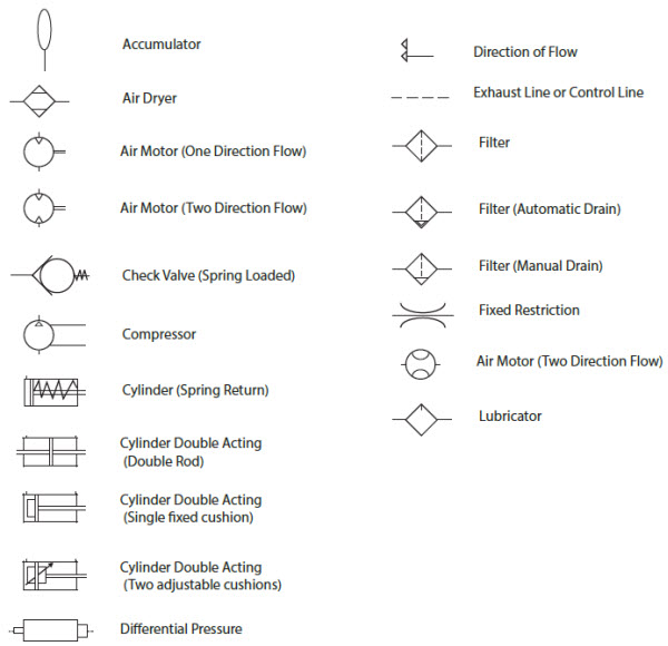
Miscellaneous hydraulic symbols and devices used in hydraulic circuit design. Dimensioning and Tolerancing with 45 elements. IEC 60617 Sample Drawing.
Direction of Flow Pneumatic. Airline Hydraulics Main Page. Spool type flow divider eg.
Discover Hydraulic Lines Basic Symbols. Hydraulic Reservoir - Open. -envelope long and short dashes around two or more component symbols.
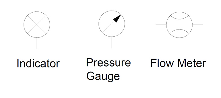
Hydraulic Reservoir - Closed. Solid Direction of Hydraulic Fluid Flow. Displayed Programmable Indicator symbol.
Compensated flow regulator 3 way. Adjusting the flow rate of fluid in a hydraulic system will directly impact. Flow indicator flow meter tachometer torque meter pressure switch micro switch adjustable 2-way flow control with reverse flow check eg.
Diaphragm Meter symbol. Please get in touch on 44 0845-644-3640. -dashed line pilot drain.
Direction of Flow - Pneumatic. As the spool moves over the internal orifice opens gradually rather than instantly as it would in. The most common hydraulic symbols are represented by the ISO 1219-12012 standard.
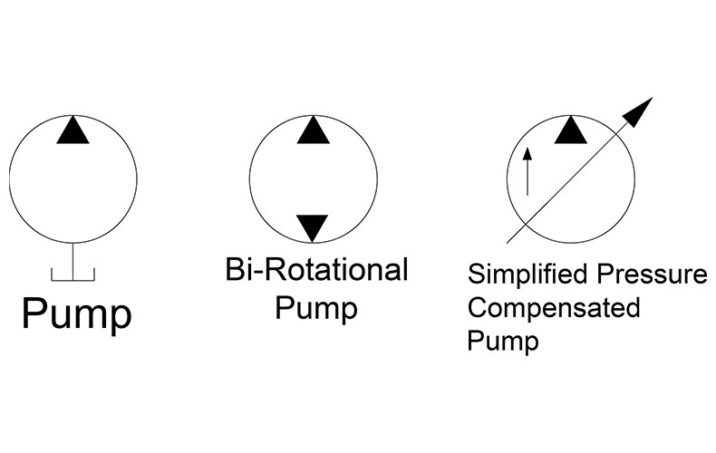
There are so many symbols to identify and lines to keep track of. Hydraulic power is based on Pascals Principle. Simplified symbols are shown for commonly used components.
AC500 PLC COMM INT Modules. The bottom symbol has a side arrow that some manufactures have used to indicate a pressure compensated valve but in ISO 1219 now means a third bypass drain line. This symbol shows a common form of flow control valve that meters the flow in only one direction only the flow will go through the check valve in the return direction.
Open Direction of Pneumatic flow. Here are a number of highest rated Hydraulic Flow Meter Symbol pictures upon internet. Ivcrd 2vcr adjustable 3-way flow control with reverse flow check eg.
Composite symbols can be devised for any fluid power component by combining basic symbols. PID PIP Sample Drawing. -continuous line flow line.
The straight lines either side of the 3 way 2 position valve show that it uses a proportional spool eg. -dashed line pilot drain. Check valve without spring.
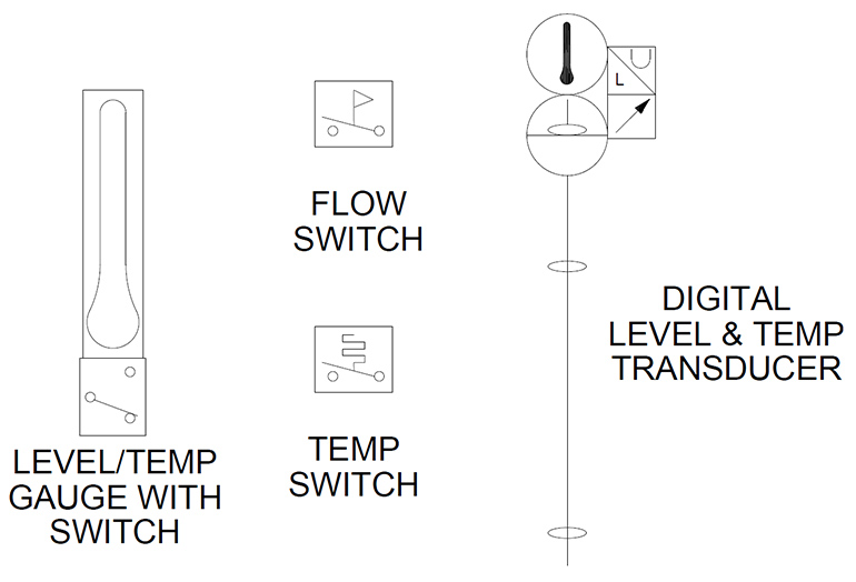
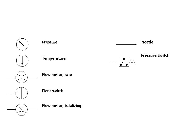
The symbol shows a fluid flow meter with digital display. This symbol shows a basic priority flow control valve which is designed to always provide flow to the main priority flow path up to a pre-set limit then supply the excess flow to the third line. I hope to impart to you a systematic approach to reading a hydraulic schematic.
-large circle pump motor. Compensated flow regulator 2 way. JIC NFPA Sample Drawing.
Learn About Other Hydraulic Basic Symbols. The top symbol shows a curved restrictor but the symbol also has a line with a dot that has previously been used to indicate temperature compensation. Explore Hydraulic Motor Pump Symbols.
The basic steps to reading a hydraulic schematic are. PID PIP Sample Drawing. Line crossing 1 line crossing2.
Our technical sales engineers will be happy to help should you need any further help and assistance. Adjusting the flow rate of fluid in a hydraulic system will directly impact the output. Flow Nozzle Meter symbol.
Mechanical Engineering solution 8 libraries are available with 602 commonly used mechanical drawing symbols in Mechanical Engineering Solution including libraries called Bearings with 59 elements of roller and ball bearings shafts gears hooks springs spindles and keys. Branching with connected pipe. Lines joining 1 line joining2.
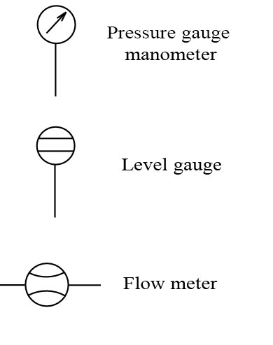
The following are ISO hydraulic reservoir enclosure and meters schematic symbols commonly used on technical drawings. -envelope long and short dashes around two or more component symbols. A guide to common hydraulic symbols.
Its submitted by government in the best field. Line Working Main Line Pilot For Control Line Enclosure Outline. For different displays or electrical communication systems the flow meter symbol would remain the same but the symbol in the square connecting box would change.
We identified it from obedient source. The following are ISO hydraulic reservoir enclosure and meters schematic symbols commonly used on technical drawings. Hydraulic and pneumatic picture symbols for fluid power schematics define their function in engineering drawings diagrams or plans.
ISO Hydraulic Reservoir Enclosure Gages and Meters Schematic Symbols. Hydraulic flow meter symbol. Pressure exerted on a fluid is distributed equally applied pressure is equal to desired pressure.
Identify if lines cross. We allow this nice of Hydraulic Flow Meter Symbol graphic could possibly be the most trending subject subsequent to we portion it in google improvement or facebook. Fluid Power Equipment containing 113.
Hydraulic Flow Meter Symbol - Hydraulic test pom plugged port rotary union detent return abovebelow fluid level check valve. JIC NFPA Sample Drawing. IEC 60617 Sample Drawing.
-continuous line flow line. As well as many other sophisticated symbols and templates for your use. 1216 This standard provides basic symbols which differentiate between hydraulic and.
Check valve with spring. Ivcrt 3vcr adjustable 3way flow control flow divider eg. Airline Hydraulics Main Page.
Hydraulic Symbols Zeus Hydratech
Flow Sheet Symbols Roy Mech
Hydraulic Symbology 305 Condition Monitoring Symbols
Hydraulic Symbology 305 Condition Monitoring Symbols

Flow Meter Hydraulic Misc
Pneumatic Circuit Symbols Explained Library Automationdirect
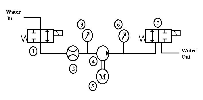
Hydraulic Circuit Schematic Showing The Location Of The Flow Meter Used Download Scientific Diagram
Hydraulic Symbols Zeus Hydratech

Design Elements Fluid Power Equipment Fluid Power Equipment Vector Stencils Library Symbol For Thermometer In Pneumatics
Hydraulic Circuit Schematic Showing The Location Of The Flow Meter Used Download Scientific Diagram
2
How To Read Hydraulic Circuits Schematic Hydraulic Symbols To Din Iso 1219

Fluid Power Symbols Ppt Download
Hydraulic Symbology 205 Hydraulic Pumps

P Id Flow Meters

Common P Id Symbols Used In Developing Instrumentation Diagrams Learning Instrumentation And Control Engineering
Engineering Projects Igloo Howard Community College Fall2012 P1 502 Lash Test Wikiversity
Hydraulic Symbols Piping And Tubing Symbols Normal Working

A Guide To Common Hydraulic Symbols Engineeringclicks